CB Power & SWR Meter
We have various SWR power meters that detect forward, reflected and VSWR power. Use it to detect frequencies, power rangers & switch from RMS or peak power.
CB Power SWR Meter Products
Filter results
Standing wave ratio
In radio engineering and telecommunications, standing wave ratio is a measure of impedance matching of loads to the characteristic impedance of a transmission line or waveguide. Impedance mismatches result in standing waves along the transmission line, and SWR is defined as the ratio of the partial standing wave's amplitude at an antinode to the amplitude at a node along the line. The SWR is usually thought of in terms of the maximum and minimum AC voltages along the transmission line, thus called the voltage standing wave ratio or VSWR. For example, the VSWR value 1.2:1 denotes an AC voltage due to standing waves along the transmission line reaching a peak value 1.2 times that of the minimum AC voltage along that line. The SWR can as well be defined as the ratio of the maximum amplitude to minimum amplitude of the transmission line's currents, electric field strength, or the magnetic field strength. Neglecting transmission line loss, these ratios are identical. The power standing wave ratio is defined as the square of the VSWR, however this terminology has no physical relation to actual powers involved in transmission.
The standing wave ratio meter, SWR meter, ISWR meter, or VSWR meter measures the standing wave ratio in a transmission line. The meter indirectly measures the degree of mismatch between a transmission line and its load.
A Must Have
The Standing wave ratio determines how good your reception and transmission will be. A perfect ratio is 1:1, the maximum acceptable ratio in CB is usually 2:1. If you listen to a 1:1 aligned radio system and a 2:1 or more you will hear an obvious difference in quality. It’s important to keep your radio system aligned not only for the quality though, a bad ratio can hurt your radio device in the long-term, sending it to an early retirement if you don’t take care of it.
Test your mobile CB radio with SWR Meters
Move your vehicle to open ground. If you have instructions that came with your specific meter device follow them. Try not to have any physical barriers such as walls or trees around you. If the ratio isn’t good, try changing your setup. Sometimes you will need to change the length of the antenna, try to do it in ⅛ increments. Try to move your antenna around, make sure it’s grounded well. This is the most important part of your configuration, determining the final position of your antenna and cables. Try not drilling anything in before you do this.
In short, a meter is required to:- Keep your radio healthy
- Calibrate your setup
- Determine Antenna positioning
- Diagnose radio problems
Best Meters for Ham Radio
Many ham radios already have built in SWR/Power meters along with other features. Consider your setup:
- How accurate do you need your SWR/Power meter to be
- How much budget do you have. Compare the price and decide on your priorities
- Which additional features do you need
SWR Power Meter for VHF
The SWR Meters for VHF tends to be a more advanced device, with power meters feature, different sensors and connectivity. These are intended mostly for base stations in ham radio configurations and come with a price. You cannot compare them to the minimal needs of CB radios who are on the HF band.
Not Sure What to Get?
What’s the best Meter for your CB
Consider small SWR meters for Standing wave Ratio. You can also connect that device to your lighter plug or to the fuse-box. Permanent In-line meters would be the easiest to install, if you compare them to equipment you only connect temporarily for check-ups
SWR for Ham/Amateur Radio
For ham radio there are many different configurations and testing equipment, usually they also include built-in power meters to measure transmissions. if you’re not sure what device to get for your configuration. Try to compare the features these products have, call us or send us a message and we’ll help you choose the best product for your setup.
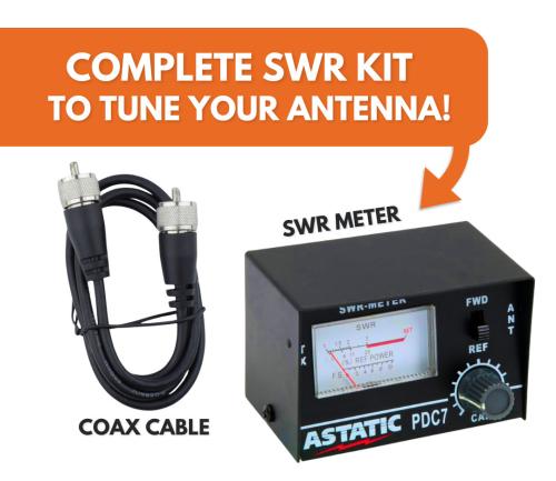
Model: Package Bundle SWRKIT
- Astatic PDC7 SWR Meter
- 3' Jumper Cable
Model: Ranger SRA-FC393
- BLUE 6 Digit Frequency Counter
- Includes Plug n Play Plug
- Similar to the FC347
Model: Nissei RS-27
- Frequency Range: 26-30mhz (CB & 10 Meters)
- Measurable power range: 0 - 1000W
- Power Range: 10W, 100W, 1000W
- Min. Power (Fwd) measured: 3W
- Connector: SO-239
Model: Dosy PM1000
- SWR and Power Meter
- Handles up to 1000 Watts
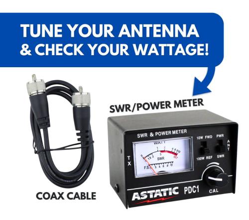
Model: Walcott Radio PDC1KIT
- SWR & Power Meter
- Includes 3' Coax Jumper
- 10 & 100 Watt Power Scales
Model: Nissei RS-102
- 3 power scales 5, 20, 200 watts
- Works with CB, 10 meter, 2 meter, and marine
- Large Illuminated Meter
- Compare to the MFJ-872
- *NOTE* Display light requires 12VDC power source (not included)
Model: Opek Technologies SWR-9
- Easy to Read LCD Display
- 1.6 - 60 MHz / 125 - 525 MHz
- 200 Watt Power Rating
- Measures FM output, and AM carrier only * Does not measure PeP *
Model: Nissei DG-103MAX
- Covers HF Band + 6 Meter, CB Frequencies As Well
- 300mW - 300W & 300W - 1200W Power Ranges
- Switchable to test on AM / SSB (Max ON) or FM / CW / FDMA (Max Off)
- *NOTE* Power Supply Not Included - Requires 1A 12VDC Power Supply
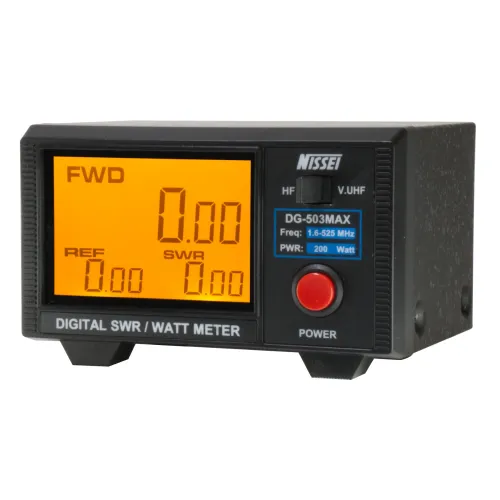
Model: Nissei DG-503MAX
- Measures Analog (FM, CW, FDMA) & Digital Modes (DMR, AM, SSB)
- Covers HF (1.6-60MHz), VHF / UHF (125-525 MHz)
- 200 Watt Power Rating
- Alternative to the MFJ-849
- *NOTE* Power Supply Not Included - Requires 1A 12VDC Power Supply
Model: Walcott Radio CBNF3AXX
- 12V Power Line Filter
- Includes 3-Pin Power Connection, Standard for most CB Radios
- Removes Unwanted RF Line Noise From Power Cord
Model: Nissei RS-40
- Frequency Range: 140-150MHz,430-450MHz
- Measurable power range: 0 - 200W
- Power Range: 15W, 60W, 200W
- Impedance: 50 ohm
- Compare to the MFJ-844
Model: Opek Technologies SWR-6L
- Frequency: 1.6 - 60 MHz (HF)
- Power Scale: 20/200/2K W
- Max. Power: 2,000 Watts
Model: Opek Technologies SWR-7L
- Frequency: 26 - 30 MHz
- Max. Power: 2,000 Watts
Model: Nissei RS-50
- For VHF / UHF Bands (125 - 525 MHz)
- Easy to Read LCD Display
- Compact & Rugged
- Compare to the MFJ-847
- Requires 2 x AAA Batteries or USB Power Source
Model: Dosy PM2001
- SWR and Power Meter
- Handles up to 2000 Watts
Model: Diamond Antenna SX-200
- SWR & Power Meter
- Frequency: 1.8 - 200 MHz
- Power Ranges: 5/20/200 Watt
Model: Ranger SRA-FC393-W
- WHITE 6 Digit Frequency Counter
- Includes Mounting Bracket & Cable
- Frequency Range: 1 - 40 MHz
Model: Opek Technologies SWR-3
- SWR / Power / Field Strength Tester
- 10 Watt & 100 Watt Switchable Power Scale
- Frequency Range: 1.7 MHz - 150 MHz
Model: Driver Extreme DRX-6030
- Includes 18" Coax Jumper
- 100 Watts Max Power
Model: Astatic PDC2
- SWR & Power Meter
- Measures up to 100 Watts AM Carrier
- Small Size at 5" wide and 2" deep
- Easy Operation
Model: Astatic PDC1
- Easy to use meter
- Test your antenna system for efficiency and problems
- Don't forget to add the coax jumper!
Model: Diamond Antenna SX40C
- Operates from 144 - 470 MHz (2 meter & 70 Cm)
- Cross Needle Design
- Power ranges of 30 & 300 Watts
Model: Walcott Radio NF40
- 20 Amp DC Power Line Filter
- Requires hard-wire
Model: Astatic PDC7
- Easy to use meter
- Test your antenna system for efficiency and problems
- Don't forget to add the coax jumper!
Model: Walcott Radio JBCNR400
Model: Dosy TR2000
- SWR and Power Meter
- 2000 Watt Capacity
- Frequency Operation: 26~27 MHz (CB Frequencies)
Contact Us
- Walcott Radio
- 2940 N Plainview Rd Walcott
- Walcott, IA 52773
- Phone Support
- 1-844-925-2688
- M-F 10am to 5pm CST
- Store Hours
- M-F 9am-6pm
- Sat 9am-5pm
- Sun Closed


